Temperatuuriga seotud jamad
Multiandur
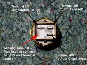
TESTING THE COOLANT GAUGE OPERATION:
If you have the original 4 terminal VDO brand sensor, make sure the +12V wiring connection (3/+) has power. You could have a blown fuse, check the
wiring diagram for your vehicle.
If you unplug the connector from the sensor and ground the corresponding terminal 1/T (BR/Y wire) in the connector, the coolant temperature gauge
in the instrument cluster should go to a max temp reading with the ign. key on.
Kui sa võtad multianduri pistiku lahti ja maandad 1/T ühenduse (pruun-kollane kaabel) pistikus, siis temperatuuri näidik kelladeplokis peaks
minema maksimum näiduni, kui süüde on sees.
Testing Other Functions of this Sensor:
Terminal 2/R provides a ground signal to the Engine Control Unit (1986-88 Audi 5000T/5000TQ and 1989-91 200T/200TQ) if the engine is running too hot
(over 247F, 119C) which will reduce the amount of boost the ECU will provide.
You can temporarily run the car with the Multi-Function Temperature Sensor connector unplugged to verify if the sensor has malfunctioned and is
causing the low boost problem.
Note: The 1992-95 Audi S4/S6 Engine Control Unit (ECU) does not use this over temp signal from the Multi-Function Temperature Sensor to lower boost
when the engine overheats, it uses the signal from the ECU coolant temperature sensor mounted at the back of the cylinder head.
The 1995 Audi S6 may not have the +12V wiring connection for this sensor (Black wire with blue stripe)
Terminal 2/R also provides a ground signal from this same connection to the A/C control head unit which also will turn off the A/C if the engine temp.
exceeds 247F.
If your engine is not overheating, and you suspect the sensor is malfunctioning, you should test this terminal 2/R connection (Blue wire with green
stripe) to ensure that it is not grounded by the sensor, from faulty wiring, or from corrosion.
The Terminal 4C connection (Black wire with Yellow Stripe) goes to the Auto Check control unit to warn of possible over heating. This wire is also
connected to the coolant expansion tank level sensor.
 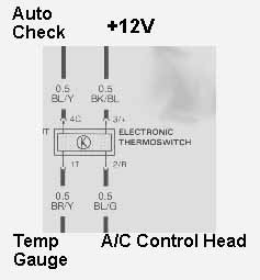
WIRING COLOR CODES
BL / Y is Blue with Yellow stripe
BK / BL is Black with Blue stripe
BR / Y is Brown with Yellow stripe
BL / G is Blue with Green stripe
Connection problems: In some cases the connector terminals can be corroded and will be causing a poor connection. The rubber boot that is supposed to
protect the connector, often times gets old and hard and allows water/coolant to fill up the rubber boot and saturates the connector terminals and can
cause corrosion problems.
Some folks have cut small drain holes in their boot if the boot is in good shape. If the boot is falling apart, I usually carefully cutoff/remove the
rubber boot from this connector, and just allow the connector to be open to the air to allow any moisture to drain off the connector.
Vehicles located in any areas that salt the roads should leave the rubber boot in place and/or replace as necessary. It is very common for the gauge
to begin working after this 4 pin connector is removed and installed due to internal sensor connections being moved on the 4 terminal version of these
MFTS.
If you remove the connector from the sending unit and look at it with the notch at the top, terminal 3 is at the upper LEFT, terminal 4 is at the
upper RIGHT, terminal 2 is at the lower RIGHT, and terminal 1 is at the lower LEFT.
Often times this plastic connector is brittle, a new plastic connector housing can be purchased from Audi, the part number is 893 971 974.
The 3 terminal version eliminated the requirement for +12V and is mechanical in operation, as it uses a thermal expanding pellet and 2 mechanical
micro-switches for the 2 overheat functions, and a regular Negative Temperature Coefficient (NTC) resistive element for the coolant temperature gauge
operation. A NTC resistive element, has a decreasing resistance with increasing temperature.
Other things to note: (5000T/Q, 200TQ) Fuse #12 supplies +12V to the Multi-Function Temperature sensor on the original 4 terminal sensors, so check
your fuses. This fuse #12 also supplies +12V to the back up lights and to the speedometer sending unit in the transmission. S4/S6, check the Bentley
Wiring diagrams for the correct fuse.
Other Failure Info: I opened up two of these 3 terminal Behr units that had failed after less than one year, and found that the inside of the sensor
was full of engine coolant. It appears that the machined brass housing somehow allowed coolant to seep into the micro switch area, right through the
threaded portion that screws directly into the coolant passage.
It is possible that over-tightening the 3 terminal style sensor is causing the brass threaded area of the sensor to crack and leak coolant into the
sensor internal contact area so don't strong arm the sensor when installing it. Torque specification is 18 ft-lbs.
Other failure ideas: possibly the brass was porous on these faulty units and allowed the coolant to seep in.....More investigation is needed......Just
our theory at the moment.
Allikas: http://www.sjmautotechnik.com/trouble_shooting/cooling.html
Termostaadi vahetusest: http://www.s2-audi.co.uk/tech_articles/thermostat_replace.htm
|